Emporia Vue2 ESPhome flash
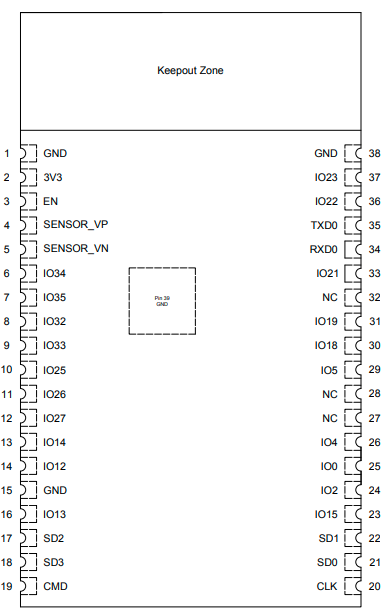
- use pins V3.3,
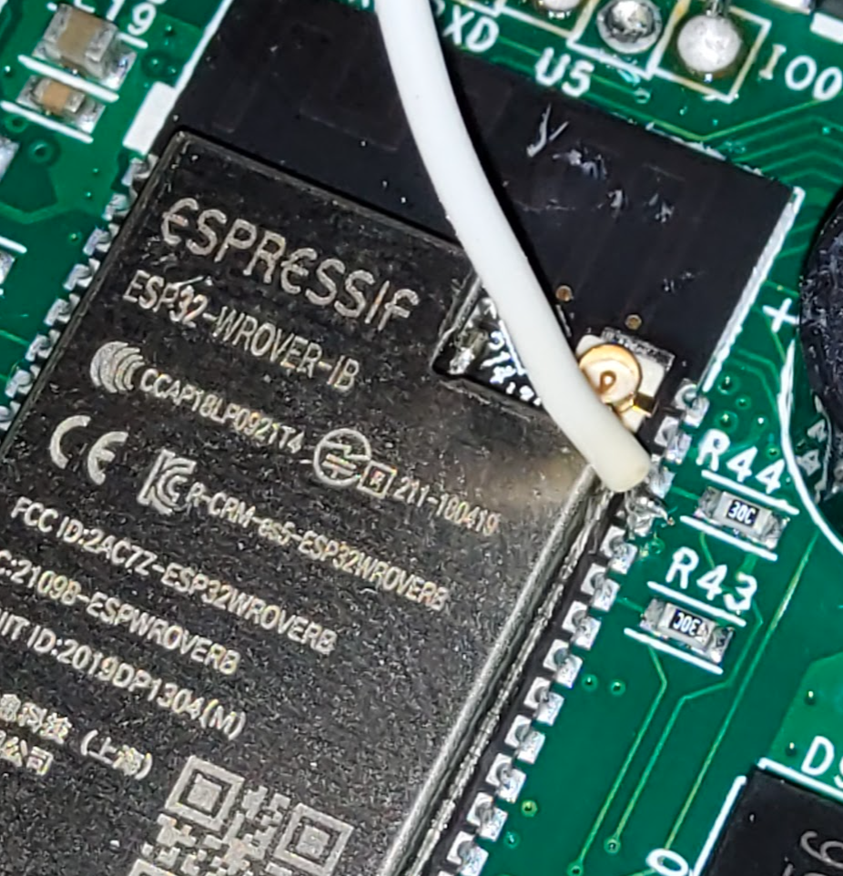
RX, TX, GND and IO0 - for the TTL RX connection, solder a thin wire directly to the TX (35) pin of the ESP32

 \\it did not work with the debug-header RX labelled pin, there seems to be some circuit between the pin on the board and the esp, my connectivity tests showed some resistance in the line. flashing using the RX pin on the debug header did not work, however it worked great with a direct connection to the ESP's RX pin
 - connect TX on the TTL adapter to TX on the vue board (the labelling on the vue device is already switched)
- I used a white PL2303 ttl converter (TR-104). in order to successfully read/write the flash i had to do the following:
- connect all wires except for the ttl's RX
- Plug-In PL2303 USB device while holding the IO0 pin to GND
- Let go of IO0
- Connect the ttl's RX to the ESP's TX pin
- run esptool.py
Backup
us esptool
pip install esptool
then create a backup:
esptool.py -b 921600 read_flash 0 0x800000 backup.bin
Config
adjust this config (especially wifi settings) .. you can always flash newer configs later via OTA, so no worries if this is not fully your config with regards to ports etc.. all we want is some running ESPhome that can connect to your network for later flashing OTA
- config.yml
esphome:
  name: emporiavue2-1

external_components:
  - source: github://emporia-vue-local/esphome@dev
    components: [ emporia_vue ]

esp32:
  board: esp32dev
  framework:
    type: esp-idf
    version: recommended

# Enable Home Assistant API
api: {"password": "<ota password>"}
ota: {"password": "<ota password>"}

# Enable logging
logger:

wifi:
  ssid: "<ssid>"
  password: "<wifi password>"

i2c:
  sda: 21
  scl: 22
  scan: false
  frequency: 200kHz  # recommended range is 50-200kHz
  id: i2c_a
time:
  - platform: sntp
    id: my_time

# these are called references in YAML. They allow you to reuse
# this configuration in each sensor, while only defining it once
.defaultfilters:
  - &moving_avg
    # we capture a new sample every 0.24 seconds, so the time can
    # be calculated from the number of samples as n * 0.24.
    sliding_window_moving_average:
      # we average over the past 2.88 seconds
      window_size: 12
      # we push a new value every 1.44 seconds
      send_every: 6
  - &invert
    # invert and filter out any values below 0.
    lambda: 'return max(-x, 0.0f);'
  - &pos
    # filter out any values below 0.
    lambda: 'return max(x, 0.0f);'
  - &abs
    # take the absolute value of the value
    lambda: 'return abs(x);'

sensor:
  - platform: emporia_vue
    i2c_id: i2c_a
    phases:
      - id: phase_a  # Verify that this specific phase/leg is connected to correct input wire color on device listed below
        input: BLACK  # Vue device wire color
        calibration: 0.022  # 0.022 is used as the default as starting point but may need adjusted to ensure accuracy
        # To calculate new calibration value use the formula <in-use calibration value> * <accurate voltage> / <reporting voltage>
        voltage:
          name: "Phase A Voltage"
          filters: [*moving_avg, *pos]
      - id: phase_b  # Verify that this specific phase/leg is connected to correct input wire color on device listed below
        input: RED  # Vue device wire color
        calibration: 0.022  # 0.022 is used as the default as starting point but may need adjusted to ensure accuracy
        # To calculate new calibration value use the formula <in-use calibration value> * <accurate voltage> / <reporting voltage>
        voltage:
          name: "Phase B Voltage"
          filters: [*moving_avg, *pos]
    ct_clamps:
      - phase_id: phase_a
        input: "A"  # Verify the CT going to this device input also matches the phase/leg
        power:
          name: "Phase A Power"
          id: phase_a_power
          device_class: power
          filters: [*moving_avg, *pos]
      - phase_id: phase_b
        input: "B"  # Verify the CT going to this device input also matches the phase/leg
        power:
          name: "Phase B Power"
          id: phase_b_power
          device_class: power
          filters: [*moving_avg, *pos]
      # Pay close attention to set the phase_id for each breaker by matching it to the phase/leg it connects to in the panel
      - { phase_id: phase_a, input:  "1", power: { name:  "Circuit 1 Power", id:  cir1, filters: [ *moving_avg, *pos ] } }
      - { phase_id: phase_b, input:  "2", power: { name:  "Circuit 2 Power", id:  cir2, filters: [ *moving_avg, *pos ] } }
      - { phase_id: phase_a, input:  "3", power: { name:  "Circuit 3 Power", id:  cir3, filters: [ *moving_avg, *pos ] } }
      - { phase_id: phase_a, input:  "4", power: { name:  "Circuit 4 Power", id:  cir4, filters: [ *moving_avg, *pos ] } }
      - { phase_id: phase_a, input:  "5", power: { name:  "Circuit 5 Power", id:  cir5, filters: [ *moving_avg, *pos, multiply: 2 ] } }
      - { phase_id: phase_a, input:  "6", power: { name:  "Circuit 6 Power", id:  cir6, filters: [ *moving_avg, *pos, multiply: 2 ] } }
      - { phase_id: phase_a, input:  "7", power: { name:  "Circuit 7 Power", id:  cir7, filters: [ *moving_avg, *pos, multiply: 2 ] } }
      - { phase_id: phase_b, input:  "8", power: { name:  "Circuit 8 Power", id:  cir8, filters: [ *moving_avg, *pos ] } }
      - { phase_id: phase_b, input:  "9", power: { name:  "Circuit 9 Power", id:  cir9, filters: [ *moving_avg, *pos ] } }
      - { phase_id: phase_b, input: "10", power: { name: "Circuit 10 Power", id: cir10, filters: [ *moving_avg, *pos ] } }
      - { phase_id: phase_a, input: "11", power: { name: "Circuit 11 Power", id: cir11, filters: [ *moving_avg, *pos, multiply: 2 ] } }
      - { phase_id: phase_a, input: "12", power: { name: "Circuit 12 Power", id: cir12, filters: [ *moving_avg, *pos, multiply: 2 ] } }
      - { phase_id: phase_a, input: "13", power: { name: "Circuit 13 Power", id: cir13, filters: [ *moving_avg, *pos ] } }
      - { phase_id: phase_a, input: "14", power: { name: "Circuit 14 Power", id: cir14, filters: [ *moving_avg, *pos ] } }
      - { phase_id: phase_b, input: "15", power: { name: "Circuit 15 Power", id: cir15, filters: [ *moving_avg, *pos ] } }
      - { phase_id: phase_a, input: "16", power: { name: "Circuit 16 Power", id: cir16, filters: [ *moving_avg, *pos ] } }
  - platform: template
    name: "Total Power"
    lambda: return id(phase_a_power).state + id(phase_b_power).state;
    update_interval: 1s
    id: total_power
    unit_of_measurement: "W"
  - platform: total_daily_energy
    name: "Total Daily Energy"
    power_id: total_power
    accuracy_decimals: 0
  - { power_id:  cir1, platform: total_daily_energy, accuracy_decimals: 0, name:  "Circuit 1 Daily Energy" }
  - { power_id:  cir2, platform: total_daily_energy, accuracy_decimals: 0, name:  "Circuit 2 Daily Energy" }
  - { power_id:  cir3, platform: total_daily_energy, accuracy_decimals: 0, name:  "Circuit 3 Daily Energy" }
  - { power_id:  cir4, platform: total_daily_energy, accuracy_decimals: 0, name:  "Circuit 4 Daily Energy" }
  - { power_id:  cir5, platform: total_daily_energy, accuracy_decimals: 0, name:  "Circuit 5 Daily Energy" }
  - { power_id:  cir6, platform: total_daily_energy, accuracy_decimals: 0, name:  "Circuit 6 Daily Energy" }
  - { power_id:  cir7, platform: total_daily_energy, accuracy_decimals: 0, name:  "Circuit 7 Daily Energy" }
  - { power_id:  cir8, platform: total_daily_energy, accuracy_decimals: 0, name:  "Circuit 8 Daily Energy" }
  - { power_id:  cir9, platform: total_daily_energy, accuracy_decimals: 0, name:  "Circuit 9 Daily Energy" }
  - { power_id: cir10, platform: total_daily_energy, accuracy_decimals: 0, name: "Circuit 10 Daily Energy" }
  - { power_id: cir11, platform: total_daily_energy, accuracy_decimals: 0, name: "Circuit 11 Daily Energy" }
  - { power_id: cir12, platform: total_daily_energy, accuracy_decimals: 0, name: "Circuit 12 Daily Energy" }
  - { power_id: cir13, platform: total_daily_energy, accuracy_decimals: 0, name: "Circuit 13 Daily Energy" }
  - { power_id: cir14, platform: total_daily_energy, accuracy_decimals: 0, name: "Circuit 14 Daily Energy" }
  - { power_id: cir15, platform: total_daily_energy, accuracy_decimals: 0, name: "Circuit 15 Daily Energy" }
  - { power_id: cir16, platform: total_daily_energy, accuracy_decimals: 0, name: "Circuit 16 Daily Energy" }
create and flash the ESPhome image
first boot the esp32 into flash mode again, then run the esphome docker container (from the directory where you stored the config)
docker run --rm -v "${PWD}":/config --device=/dev/ttyUSB0 -it esphome/esphome run config.yml
if it does not succeed to flash the ESP, it will show a esptool command which can be run outside of the docker container to flash the esp.. just remove the /config/ part from the path, so something like this:
esptool.py --before default_reset --after hard_reset --baud 115200 --port /dev/ttyUSB0 --chip esp32 write_flash -z --flash_size detect 0x10000 .esphome/build/emporiavue2-1/.pioenvs/emporiavue2-1/firmware.bin 0x1000 .esphome/build/emporiavue2-1/.pioenvs/emporiavue2-1/bootloader.bin 0x8000 .esphome/build/emporiavue2-1/.pioenvs/emporiavue2-1/partitions.bin 0x9000 .esphome/build/emporiavue2-1/.pioenvs/emporiavue2-1/ota_data_initial.bin
now reboot the Vue without grounding IO0, so that it boots normally.. it shoould now connect to your wifi, if that's the case, use ESPhome's web gui to check the console and see if it's working. for this run the docker container like so:
docker run --rm --net=host -v "${PWD}":/config -it esphome/esphome
then connect with a browser to http://localhost:6052 and on your device click on “logs” –> “wirelessly”. it should now be able to connect (as long as you're in the same network as the device) and show you the link state etc… don't forget to connect the antenna the esp has a very weak internal antenna.
once this worked, you can now desolder the cables and put the Vue 2 back into its housing.